Discover Freudenberg S.A.F.E.air
S.A.F.E.air Cabin Pressure Monitoring
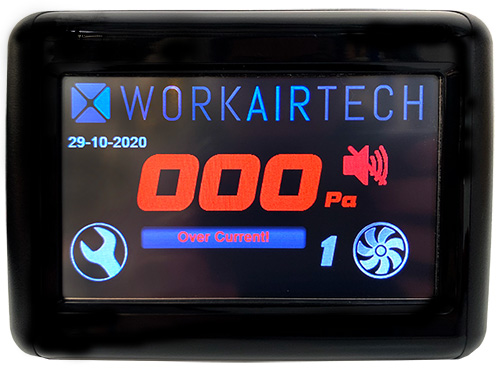
The S.A.F.E.air cabin pressure monitor measures pressure inside the cab and compares it with atmospheric pressure. When the pressure in the cab drops to a level that is not high enough to prevent dust and other materials entering the cab, the display turns red and triggers an audible alarm output to alert the operator. Pressure alarm points and delay times are user definable.
Cabin Pressure Monitoring
Overview
The touchscreen cab pressure monitor measures pressure inside the cab and compares it with atmospheric pressure. When the pressure in the cab drops to a level that is not high enough to prevent dust and other materials entering the cab, the display turns red and triggers an audible alarm output to alert the operator. Pressure alarm points and delay times are user definable.
A precision sensor allows pressure to be measured to a resolution of 1Pa or 0.1mm H2O. Measured pressure is temperature compensated to allow operation over a wide range of temperatures. An extremely high sensor burst pressure of 5000Pa means that door slams will not affect the sensor.
Push fittings allow for easy, reliable installation of the tube to the outside atmosphere. A filter is fitted to the end of the sensing tube to keep the sensor clean and dust free.
The pressure monitor is capable of integration with other systems.
0-10 volt analog output for telemetry systems
Dusttrak monitor alarm input
Spare user definable alarm input
PID pressuriser control
RS232 card reader for use instead of the password screen
RS485 Communication bus used on Work Air Tech electronic control systems
Operation
Overview
The touchscreen pressure monitor will measure cab pressure whenever the unit is powered.
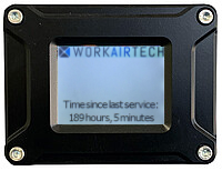
On system start up a white screen displaying system hours since service will be displayed. After several seconds the screen will display the measured cabin pressure. A single tap of the white start up screen will take the user to a password screen to access all user definable settings.
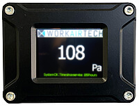
If cab pressure is above the defined minimum the display will show the cab pressure in large white characters. The lower right corner displays the unit of measure i.e. Pa, mm H20, mBar. Across the bottom of the screen in green will be a message saying “System OK” and the time since service will be displayed.
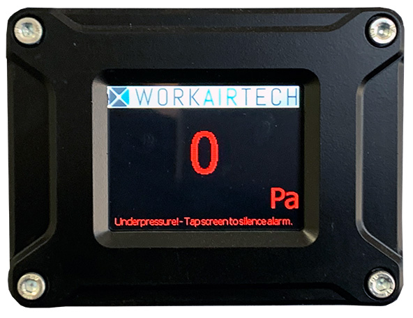
If cab pressure drops below the defined minimum for the defined delay time the characters will turn red and an audible alarm output is triggered to alert the operator. A red message across the bottom of the screen gives the operator the option to tap the screen to silence the alarm. The characters will remain red until the cab pressure rises above the defined minimum. “Underpressure” will be displayed in red if the audible alarm has been silenced.

A maximum pressure can also be defined. This is useful to alert the operator to a pressuriser filter element failure. Removing the restriction of the filter from the pressuriser fan will result in high cab pressure. In this instance the monitor will display “Overpressure” in red and the audible alarm output will be triggered. Tapping the screen will silence the alarm.
On light vehicle electronically controlled filter units the revolving beacon switch is used to determine if the vehicle is on or off site. If the beacon switch is on the audible alarm function is active. If the beacon switch is off “City mode” will be displayed at the bottom of the screen and the audible alarm function is disabled to prevent nuisance alarms.
Electrical Specifications
Operating pressure range: 0-500Pa (0-50mm H2O) Sensor resolution: 1Pa (0.1mm H2O)
Sensor burst pressure: 5000Pa
Voltage: 9-36 Volts
Current consumption: Less than 2W (100mA @ 12V, 50mA @ 24V)
External OC output: Normally open collector, switches to ground if under or over pressure, 200mA limit
Analog output: Range 0-10V, maximum 10mA output current
Environmental SpecificationsOperating temperature: -10°C to 55°C
Physical Dimentions
Dimensions: 90mm(W) x 76mm(H) x 33mm(D) Panel cut out: 77mm(W) x 57mm(H) Attachment: 4 x 4mm
Special Functions and User Definable Settings
To access the settings screen, tap the white screen during system start up.
A password screen will be displayed. Press enter to continue to the settings screen or back to return to the pressure monitor main screen.
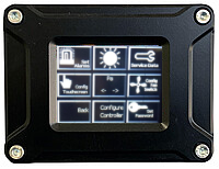
The following settings are user definable:
High and low pressure alarm points with a timed delay
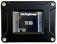
Screen brightness
Service data
Touchscreen capacitive touch calibration
Unit of measure
Fan speed control for electronically controlled filter units
Pressuriser PID control
Setting the password
Unit Of Measurement
Tapping the small arrows on the centre icon will toggle the unit of measure. The monitor can display;
Pascals
mmH2O
in. H2O
Millibar
Milliatmosphere
PSI
mmHg
in.Hg
Configeration of the Fan
The configure fan switch function is used to set recirculation fan speeds on Work Air Tech electronically controlled filter units.
Configuring the Controller
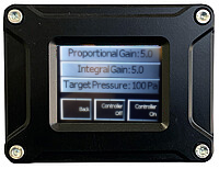
The configure controller screen can be used to control the pressure output of a pressuriser unit so that it maintains a set pressure inside the cab. Pressing the configure controller icon displays the target pressure, the proportional gain and integral gain used in the PID to control cab pressure.
Setting The Password
Pressing the set password icon will access the set password screen.
Input the desired password and press enter. If a password is set and forgotten the monitor will require reprogramming.

Want to know more about S.A.F.E.air or have a question?

For an audit
S.A.F.E.air Air Filtration and Pressurisation systems
SIMPLY FILL OUT THE FORM WITHOUT OBLIGATION
 Language / Country


